The Solid Steel Yarn Winder
This is a bit of a strange direction for this blog to take! Over the past few years, I've taken up machining as a hobby. I've found that machining is incredibly emotionally restorative for me and I've really come to love it. I'm still heavily involved with Linux and networking and container orchestration and all that jazz, but metalworking has captured my interest in a way nothing else ever has. So, onto the meat of this!
I made my girlfriend a yarn winder for her birthday. She had always wanted one but had never gotten to digging around. I wanted to get her one, but quickly found that I wasn't happy with the commercially available winders out there. They were all either cheap plastic garbage or expensive wooden things. I wanted to get her something nice, but I had my reservations. I liked the wooden winders, but there were some key components I felt should have been made out of metal. This wasn't available, so I decided I would build the most overkill yarn winder possible -- one made from solid 4000 series alloy steel. This post is going to cover the build process. First, I'd like to go over some background info and what a yarn winder is.
Yarn winders
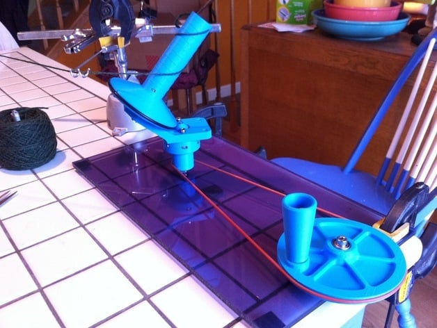
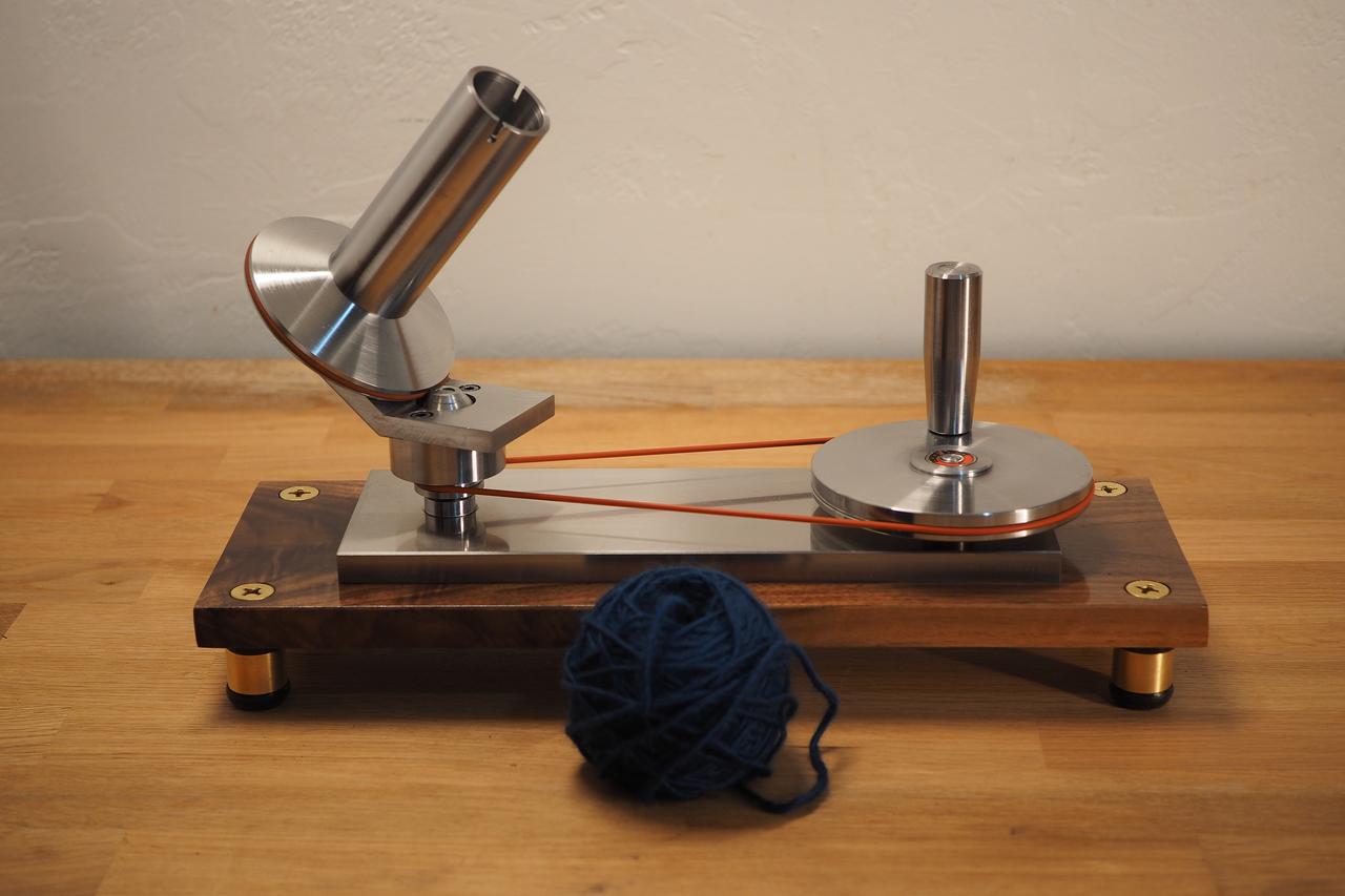
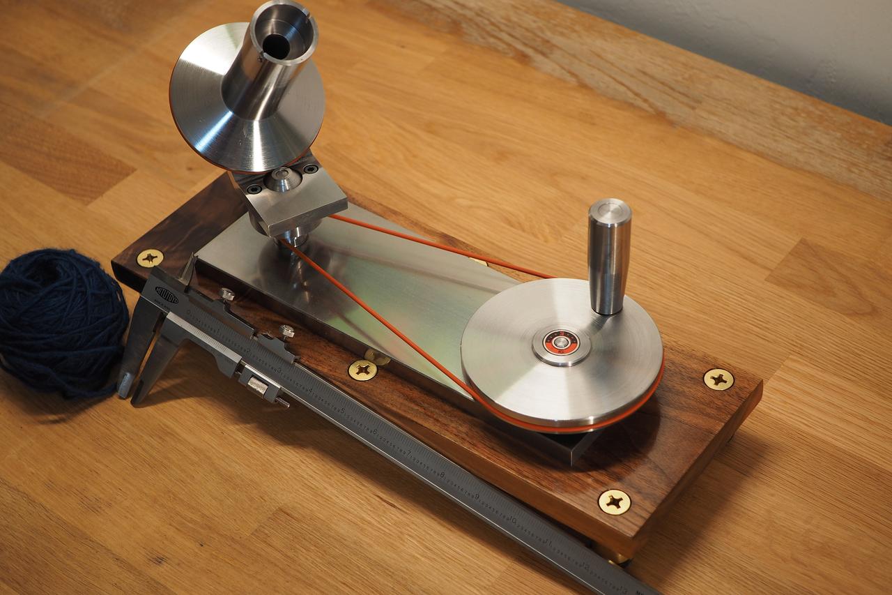
A lot of the folks reading this might not know much about yarn winders. It's easy to figure out what they do based on the name, but they're actually a bit more complicated than you might expect. When I saw my first yarn winder, I didn't get why it looked the way it did:

You'd expect a yarn winder to be something like a vertical tube that just spins to wind up a ball of yarn, so the arrangement above seems a little overcomplicated. There's the large, angled bracket that spins around a stationary peg. The yarn spindle is attached to that angled bracket with a bearing, meaning it can spin freely. The spindle disc is pushed up against the peg in the middle, meaning it also spins as it's whirling around. Here's a video that shows the effect in slow motion:
The disc in this video has a large black sharpie mark on it, showing the slow rotation of the spindle as the whole angled bracket spins around.
This compound rotation leads to balls of yarn that are relatively consistent in size and can be used from the center out. Rather than pulling the yarn from the outside (which makes the ball wobble around obnoxiously), you can pull the yarn from the center. You can also take large balls of yarn and split them up into smaller, more manageable balls, which is useful for knitting or crocheting projects with many different colors. A yarn winder is also essential when you have fancy yarn that comes on unwound "hanks," since using an unwound hank is very, very frustrating.
I've probably left out some crucial details or other great uses here, but I've only dabbled with crochet. Onto the design and build!
Design
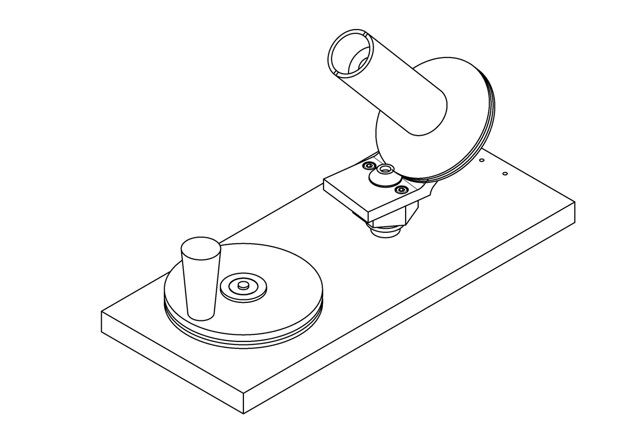
I am not a mechanical engineer. It's actually worse than that, since I'm not really mechanically inclined at all. I didn't want to design my own winder and have it crash and burn, so I decided to copy an existing design. Here's what I started with.
This looked like a nice, simple design. There were some features that were clearly targeted towards 3D printing, but most parts seemed like they'd be easy enough to machine. What really sold me is that the designer included STEP files, meaning it would be a cinch to remodel the thing for machining.
Here's what I arrived at:
It's generally similar, although I made these changes:
- The drive pulley doesn't have those weight-saving spokes
- Fasteners now thread directly into parts, rather than relying on nuts
- The bearing shafts are now proper shafts and not screws
- The 624 and 606 bearings have been replaced by 608 bearings
- The spring-loaded drive cone has been redesigned to actually function as intended
- The handle spins in an oilite bronze bushing and is retained by a circlip, rather than a bearing and a fastener
There are probably other changes I've made and forgotten about, so I'll edit this post if I think of them.
Build
This build took a while. I'm not a very good machinist, I don't have a lot of tools, and the tools I do have tend to be pretty small and/or cheap. I'm also not very good at remembering to take pictures, so there are going to be parts that are just a lot of text.
The first part I decided to make was the angled bracket.
Have you ever decided to do something the hard way? I decided to do this the hard way. The stupidly, terribly, awfully hard way. First, I lopped off a chunk of some 4340:
Then I squared up the stock on my lathe and brought it to size:
I used my lathe because my mill (a Grizzly G8689) is not up to the task of removing 0.250" of 4340 steel. And yes, I am using carbide for this hideously interrupted cut. I probably burned up about $30 worth of inserts when squaring up this stock. I didn't have a bench grinder and I haven't yet learned how to properly sharpen HSS tools. I did go out and buy some HSS inserts later on, but I wasn't using them here.
After the block was to size, I drilled and bored the central hole on the lathe, and then moved over to the mill to drill the clearance holes for the socket head cap screws. I then marked out the stock:
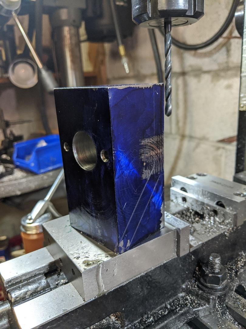
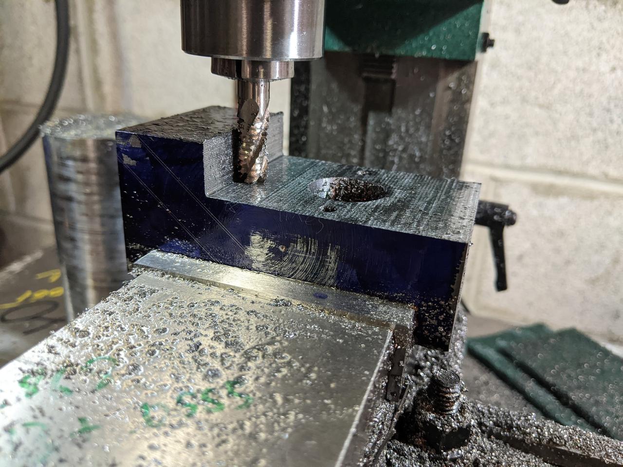
I then set about milling the stock down to the lines.
This took forever. This was seriously the WORST way I could have gone about this. Remember when I said my mill wasn't up to the task of removing 0.250" of tough steel? That didn't stop me from using it to machine away 0.500". This was just
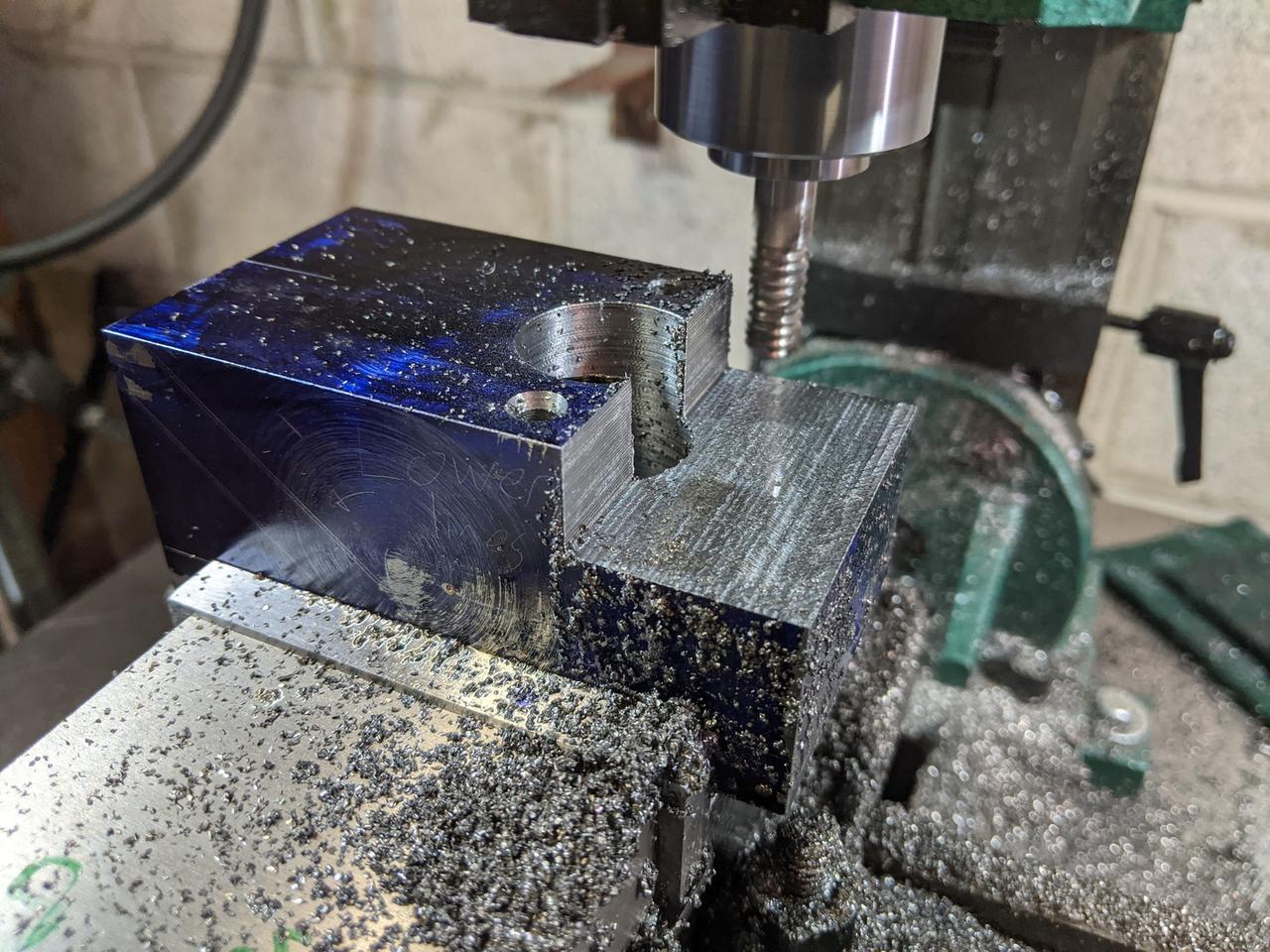
really
awfully
TERRIBLY slow.
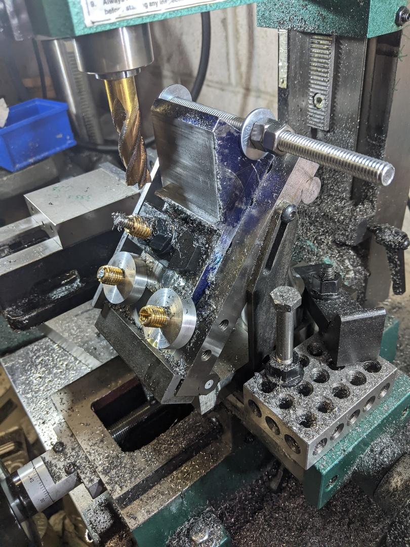
Pictured here is my cool little sine table I picked up from a retiring tool and die maker. What's less cool is my clamping system. I'm using 1/4"-20 all-thread and some brass threaded inserts as nuts. I guess I didn't have any 1/4-20 hardware, so I made due with what I had. Other problems include a dull cutter made even more dull by constant rubbing, a setup with crappy rigidity, a mill that could only take .020" cuts at a time, and a lack of cleanliness. I really should have been cleaning up some of these chips as I went along.
Eventually, I got it to the line, but I don't have any photos of that. I was so tired and done by this point that I just failed to capture anything for a while.
You might be asking yourself one of these questions:
- Why didn't you just make this out of two pieces and then fasten them together?
Honestly, because that's just not as cool. I wanted this to be a single, fully machined piece of metal - OK, so why not weld it?
Because I don't know how to weld, and the only welding equipment I have is an old oxy-acetylene rig. - Fine, why not bend it and then machine it?
I don't have any bending equipment, nor do I have the space for it. - OK buddy, why not just use a saw to remove the bulk of the material?
I don't have a vertical bandsaw to do that. My horizontal bandsaw is horizontal only, and I don't know anyone who owns a metal-cutting vertical bandsaw.
The right thing to do probably would have been to ask a local machine shop to just deck off a bunch of the material on a big mill or saw, but I was doing this during the middle of a global pandemic and I didn't feel particularly social.
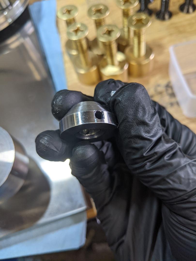
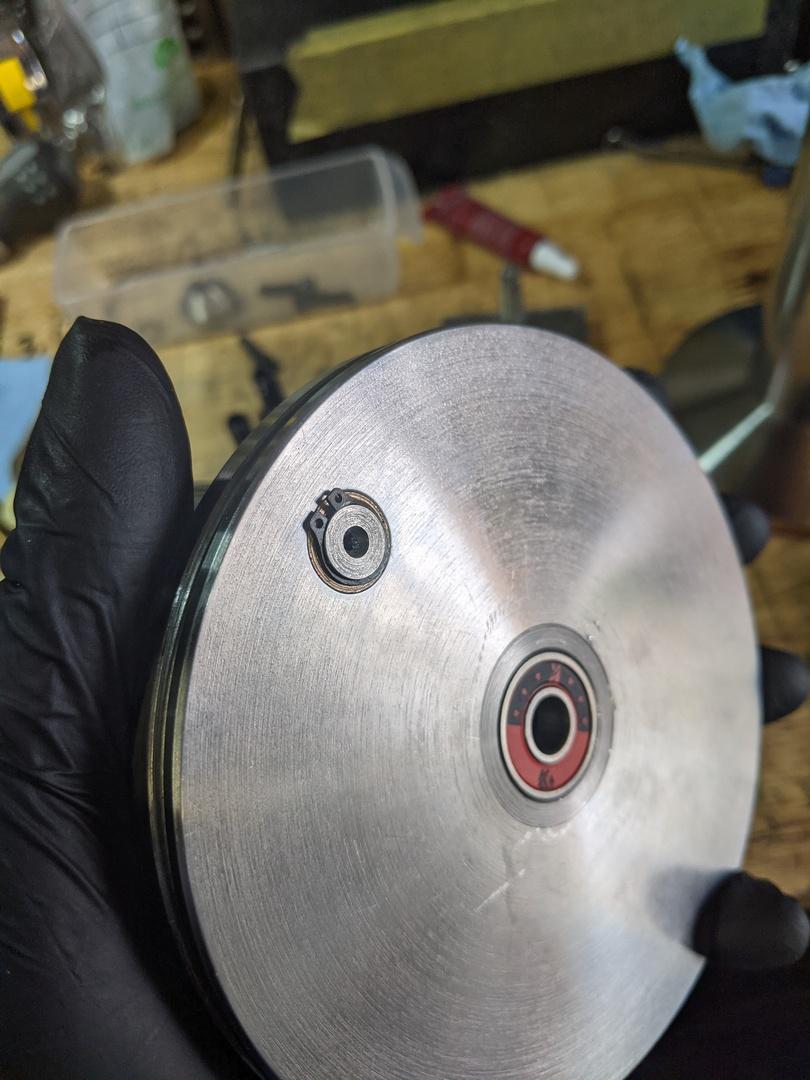
The rest of the build is mostly focused around bearing fits. First up was the disc that rides on the drive cone and spins the yarn spindle slowly:
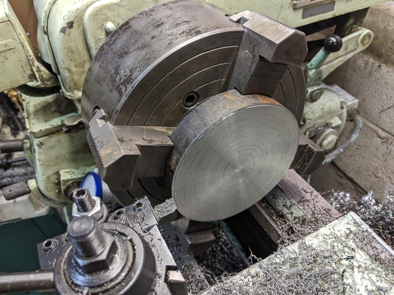
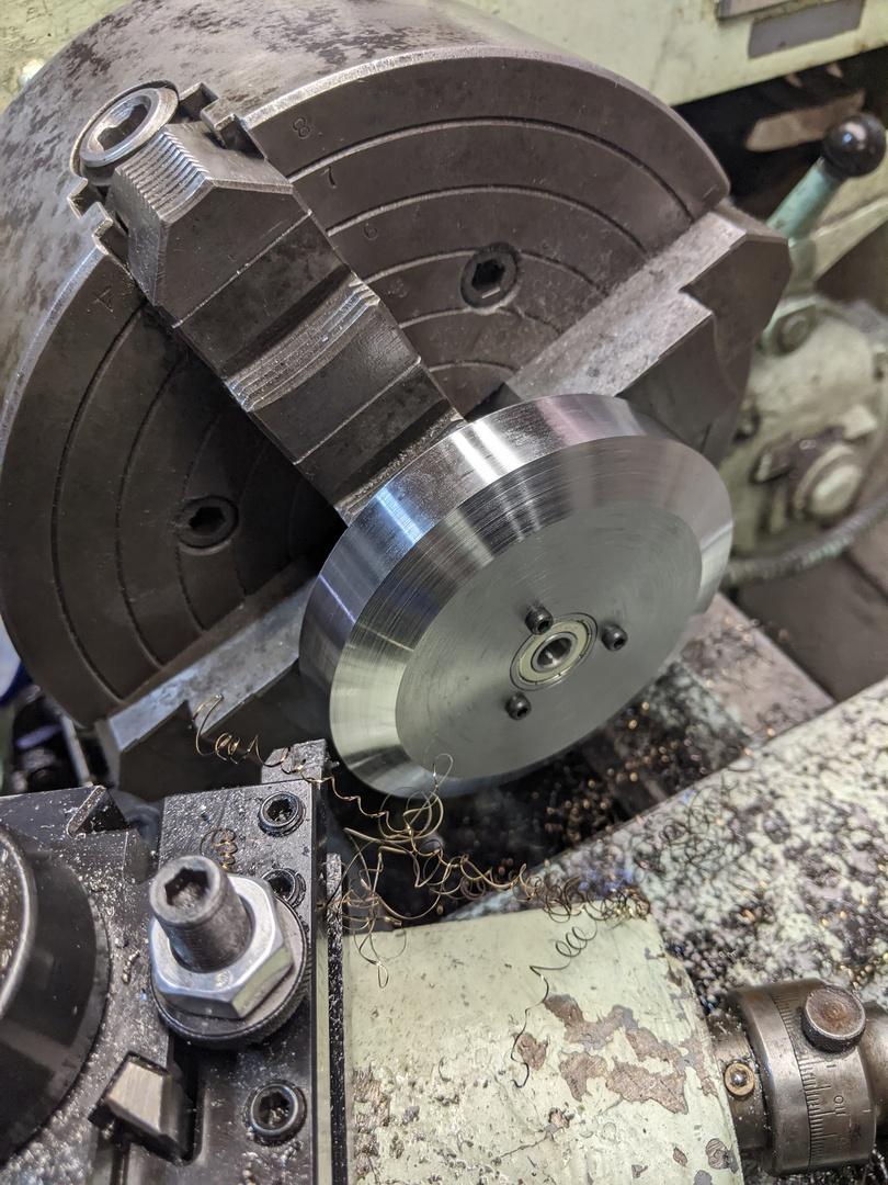
You can see in the above photo that a bearing has been pressed in, and I'd like to take a moment to talk about how I underestimated how difficult it is to make a good bearing fit.
Bearings are incredibly precise things. They can spin crazy fast and perform incredibly well, but you need to make sure that they're being held correctly. In the case of a 608 bearing where the middle shaft is stationary and the outer housing spins under heavy load and low speeds, the shaft needs to be 0.3150" exactly. The housing that the bearing is pressed into has to be 0.8661" exactly, which is not easy to do on a lathe from the 1950s. I didn't grab any pictures from making the bearing housing, but it took well over two hours of careful measurement and small cuts with a boring bar. I managed to nail every single bearing housing fit, although I did screw up and make the bearing shaft for the yarn spindle .0002" small.
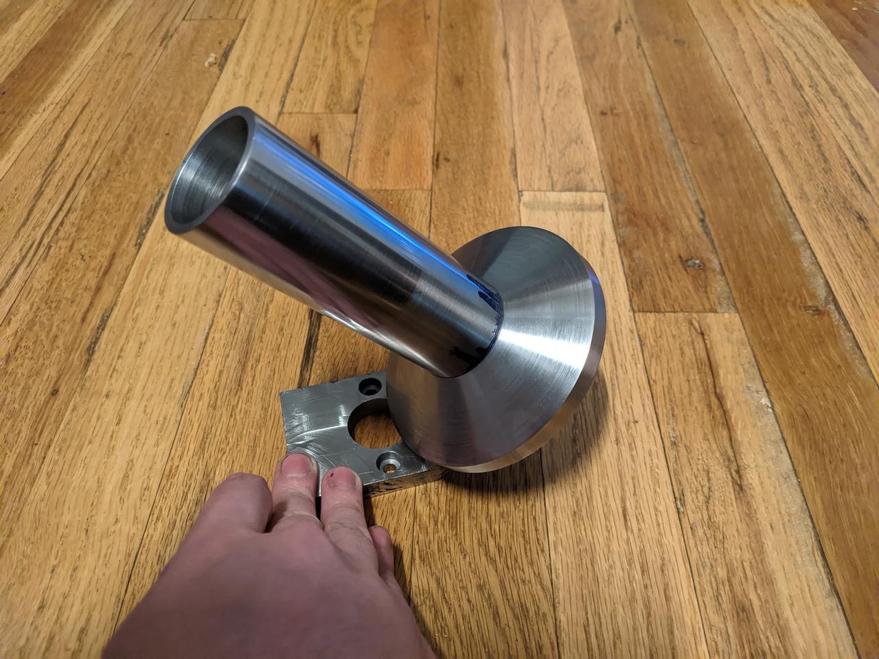
I didn't get photos of making all of these parts, but here's the angled bracket, the disc, a small bearing shaft, and the yarn spindle all together:
After this, I started making the "pulley", spring loaded drive cone, and drive shaft that all of this rides on. Here's a video of some nice chips I was getting when machining the drive shaft:
I didn't really get any good photos of this at the time, so here's some pictures from the future of how this all works.
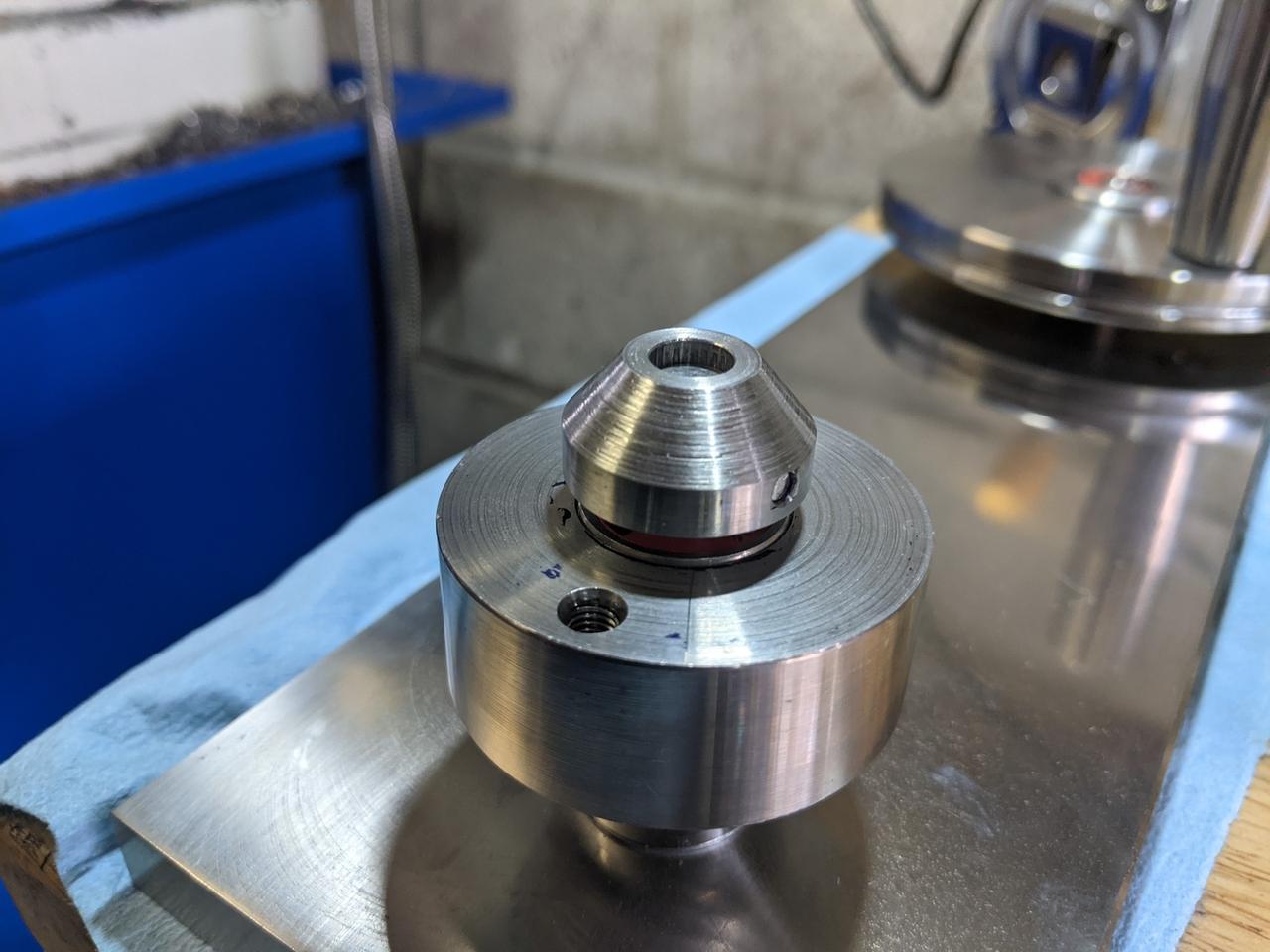
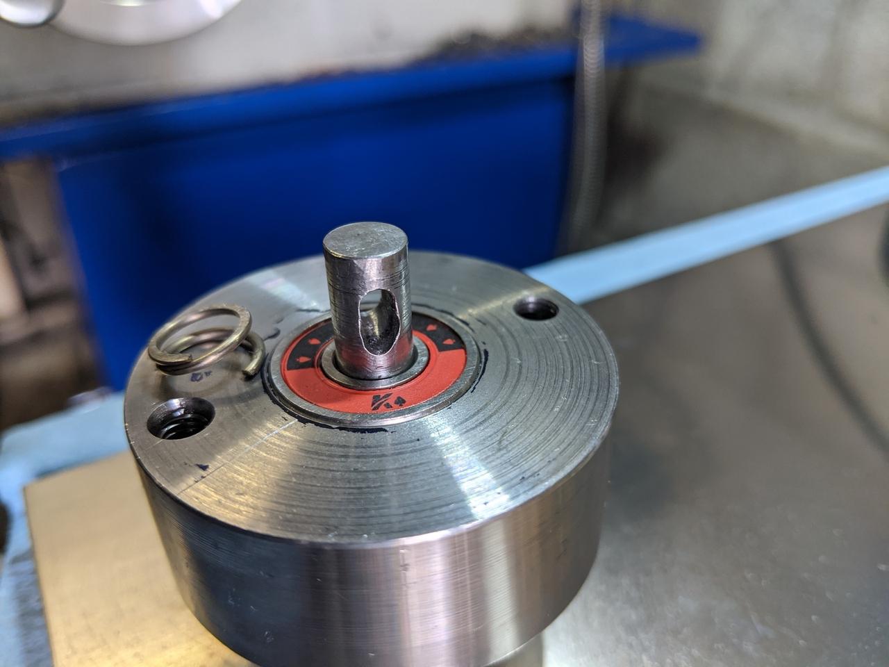
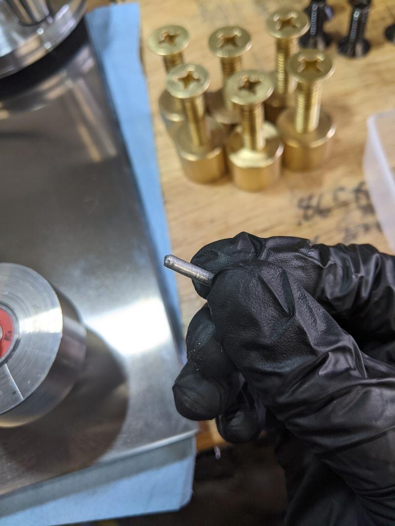
There are 5 parts in this photo: the "pulley" (the large part with the threaded holes that spins on those bearings), the drive cone (stationary), the drive shaft (stationary), a spring, and a pin. The drive shaft has a (very sloppy) slot milled in it:
The drive cone sits on a spring which rests on top of the inner race of that bearing:
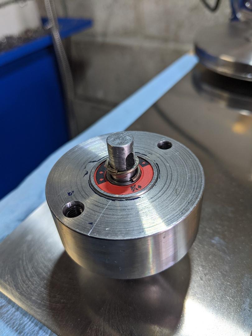
The drive cone is then retained by a small pin:
This keeps the drive cone from spinning, but lets it push up hard into the yarn spindle disc. It's a pretty neat little mechanism! It doesn't seem to work right in the original design, so I made a few tweaks here to get it functional.
At this point, the yarn winder project was put on hold while I made a set of Olympic-style dumbbells for my sister. My shop is also completely unheated, so I wasn't motivated to get back out for several months during the winter, and this is where the number of in-progress pictures really took a turn for the worse.
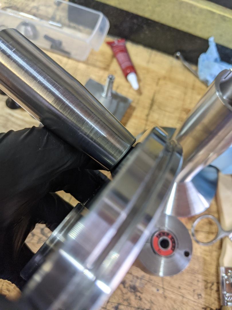
After getting back out to the shop, I made the drive shaft for the main drive pulley:
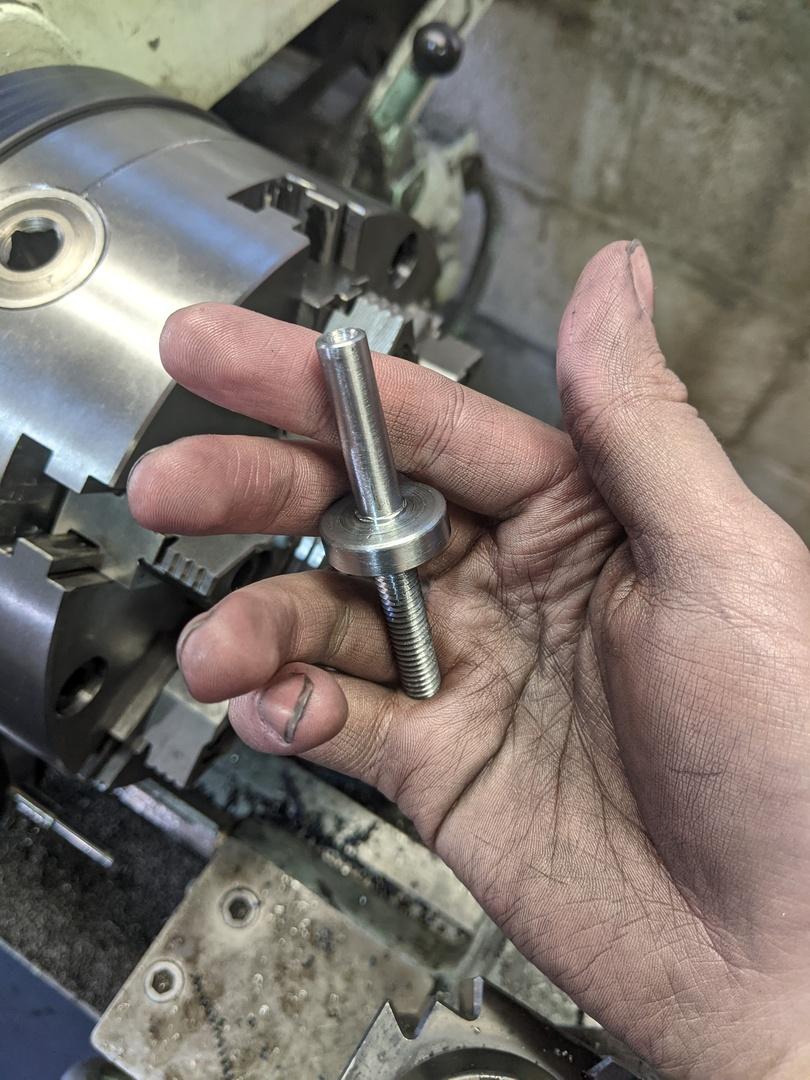
The bearing shaft and threads were overly long, but I wanted to hold of on cutting them to length until after the drive pulley and base plate were done as I was contemplating some design changes.
This is literally the only photo I have of making the main drive pulley 😅:
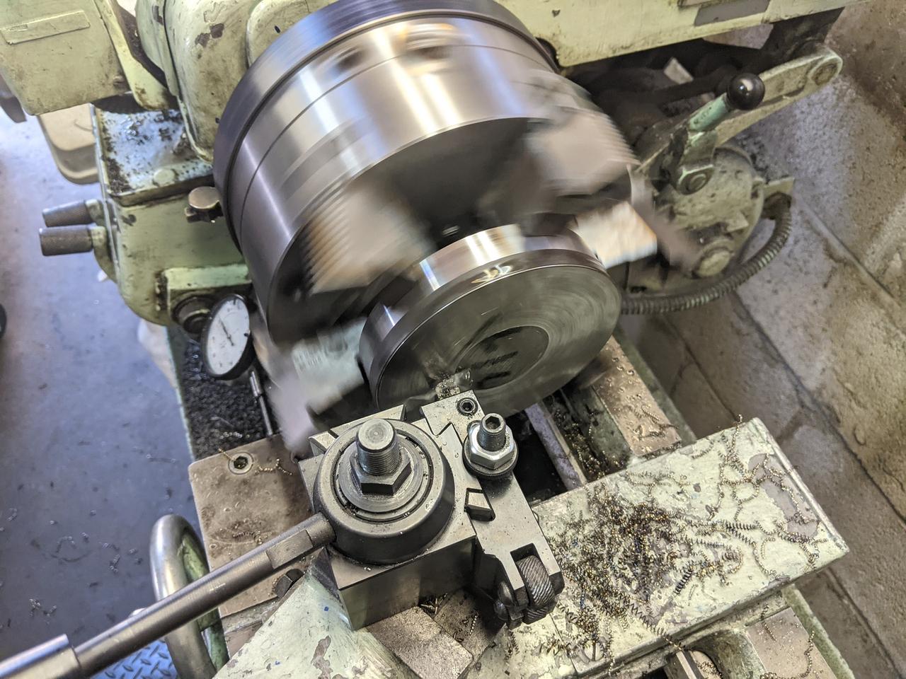
This also had two bearings in it, as well as a 0.500" reamed hole for a bronze oilite bushing. I made a handle with a 0.499" shaft to ride in that bushing. There's a small groove on one side for a circlip:
The original design just had the winder attached to a piece of plastic or wood. I had initially thought that would have been fine, but I realized around this point that the winder mechanism was too heavy and off-balance for this to work. I decided I'd make a metal sub-plate that would provide some rigidity for the machine and reduce the stress on the wood.
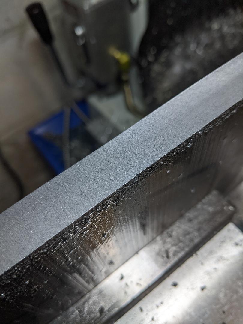
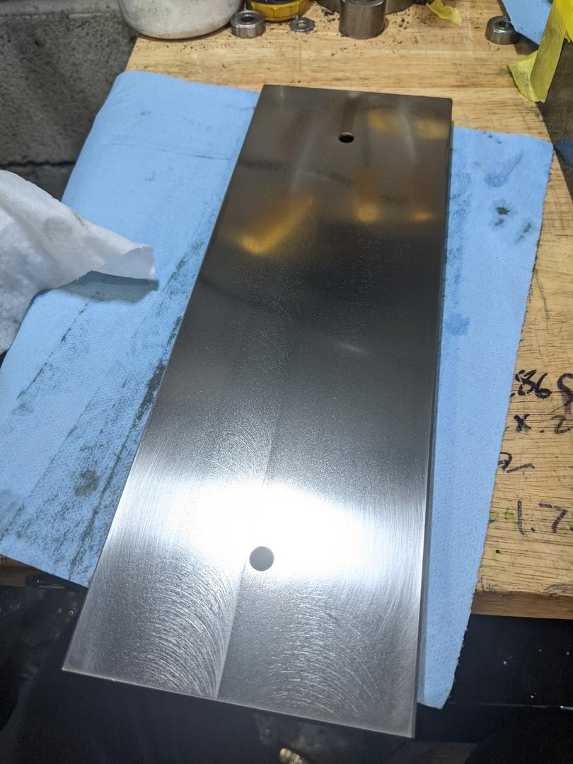
I grabbed what I thought was some steel and started machining. The piece I had was too large to fit in my horizontal bandsaw and I didn't feel like being shaken to death by my Skilsaw, so I set it up on the mill:
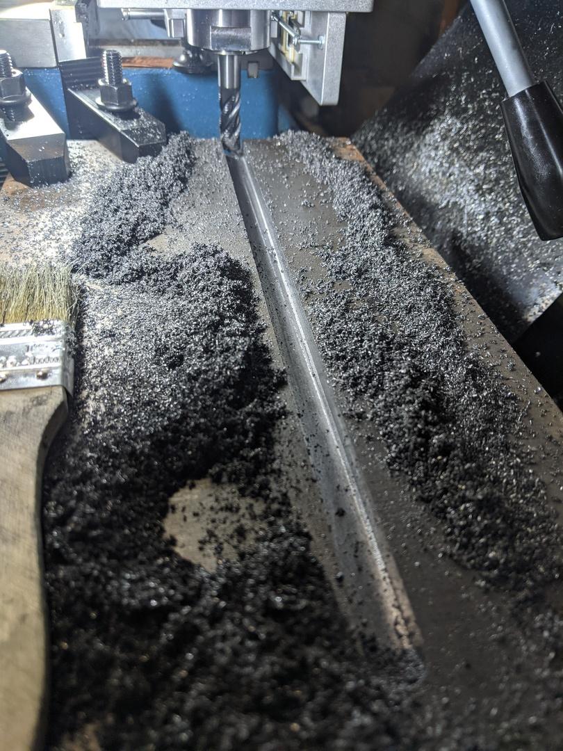
That's a 1/2" solid carbide rougher, slotting .075" at a time through this random piece of plate. This is on my shiny, shiny new Precision Matthews PM-728VT so I don't have to water-torture my way through this stock.
You can also probably tell from the chips that this isn't steel, it's ductile iron. I had been using cutting oil, so gritty iron shavings got everywhere and I'm still cleaning them up.
After I had the stock roughly to size, I needed to get it down to final dimensions and try to leave a nice surface finish. I had received this ridiculous cutter as a part of an eBay lot, so I figured I'd give it a go:
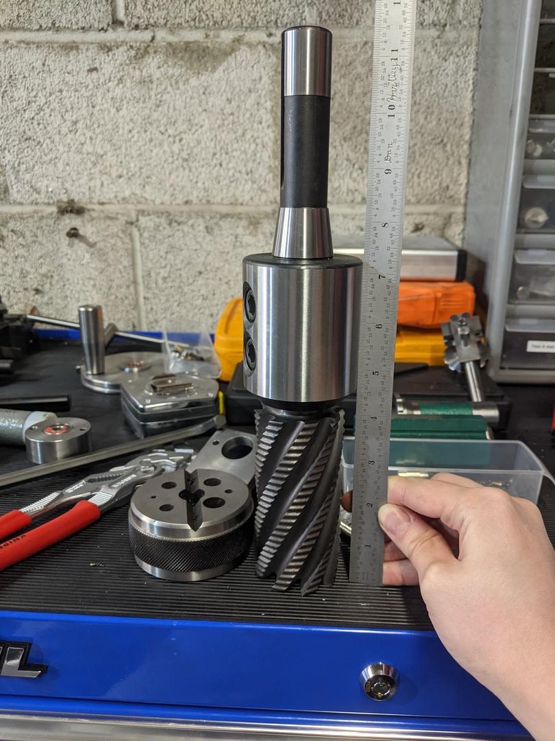
I mean, just look at this glorious ladder of steel! It's a 2" Niagara roughing endmill and it's hilariously large for my machine. I mounted it up in my mill and got to machining:
Nice and smokey. The cutter was super sharp and left a pretty good finish on the sides:
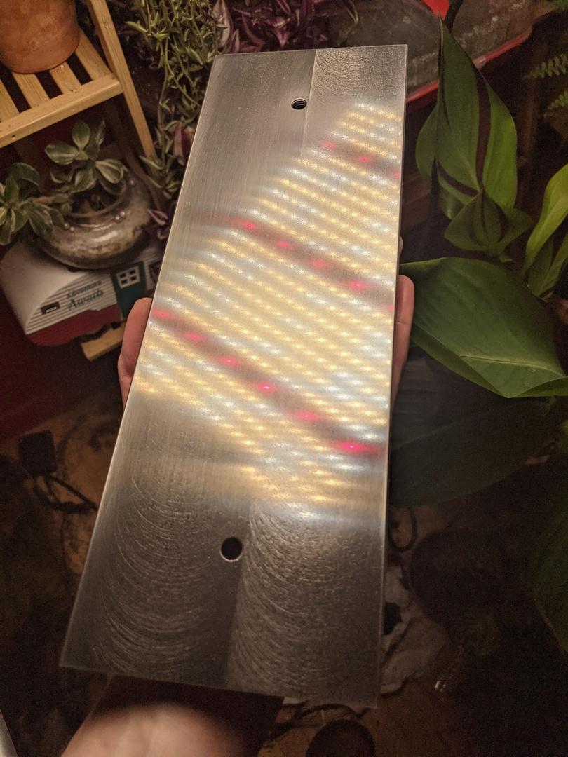
I flipped to the faces, and the story wasn't as good...
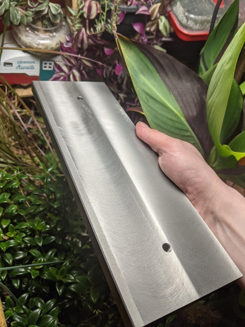
So then I got to spend a lot of time at the lapping plate. This is a surface plate dedicated for lapping with sandpaper, so don't be alarmed:
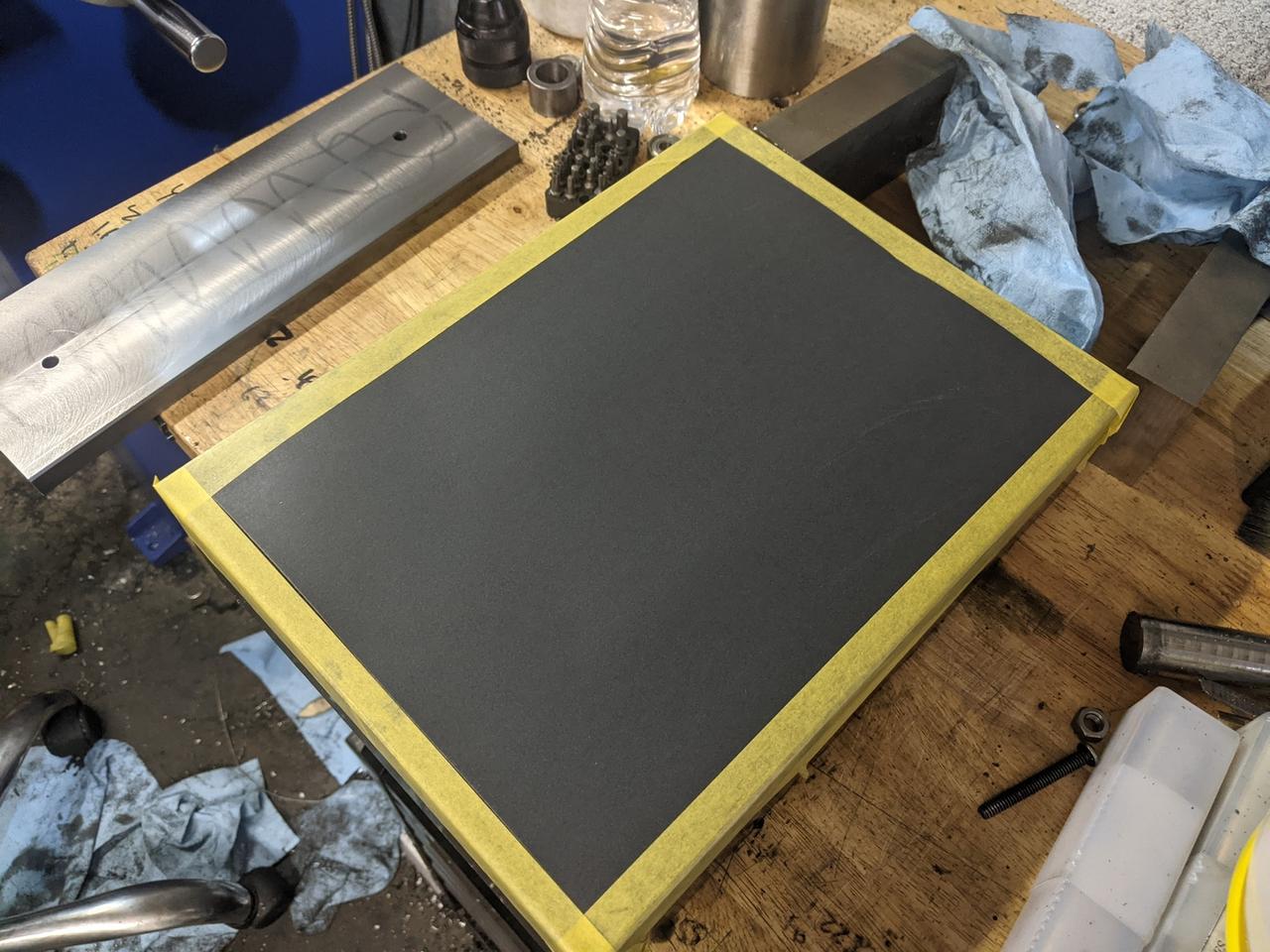
I spent a lot of time here. All told, it took 10 hours of lapping to remove most of the tool marks on this piece of ductile iron. It looks like my mill head was out of tram, meaning my cuts weren't flat. Here are some progress pictures:
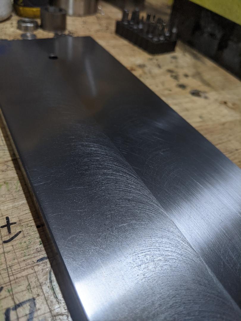
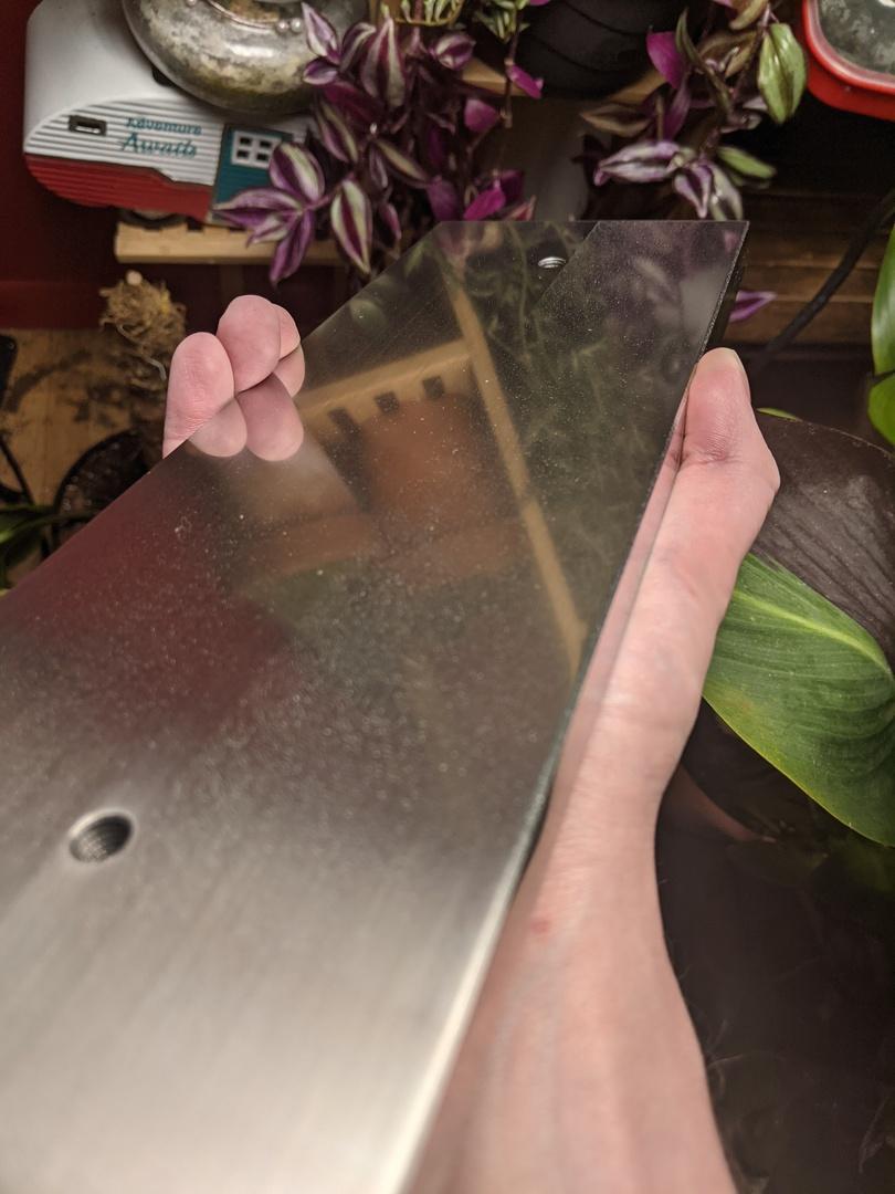
And that's where I left it. There are still some tool marks on the ends of the part, but my back was starting to hurt from all the lapping I was doing so I called it.
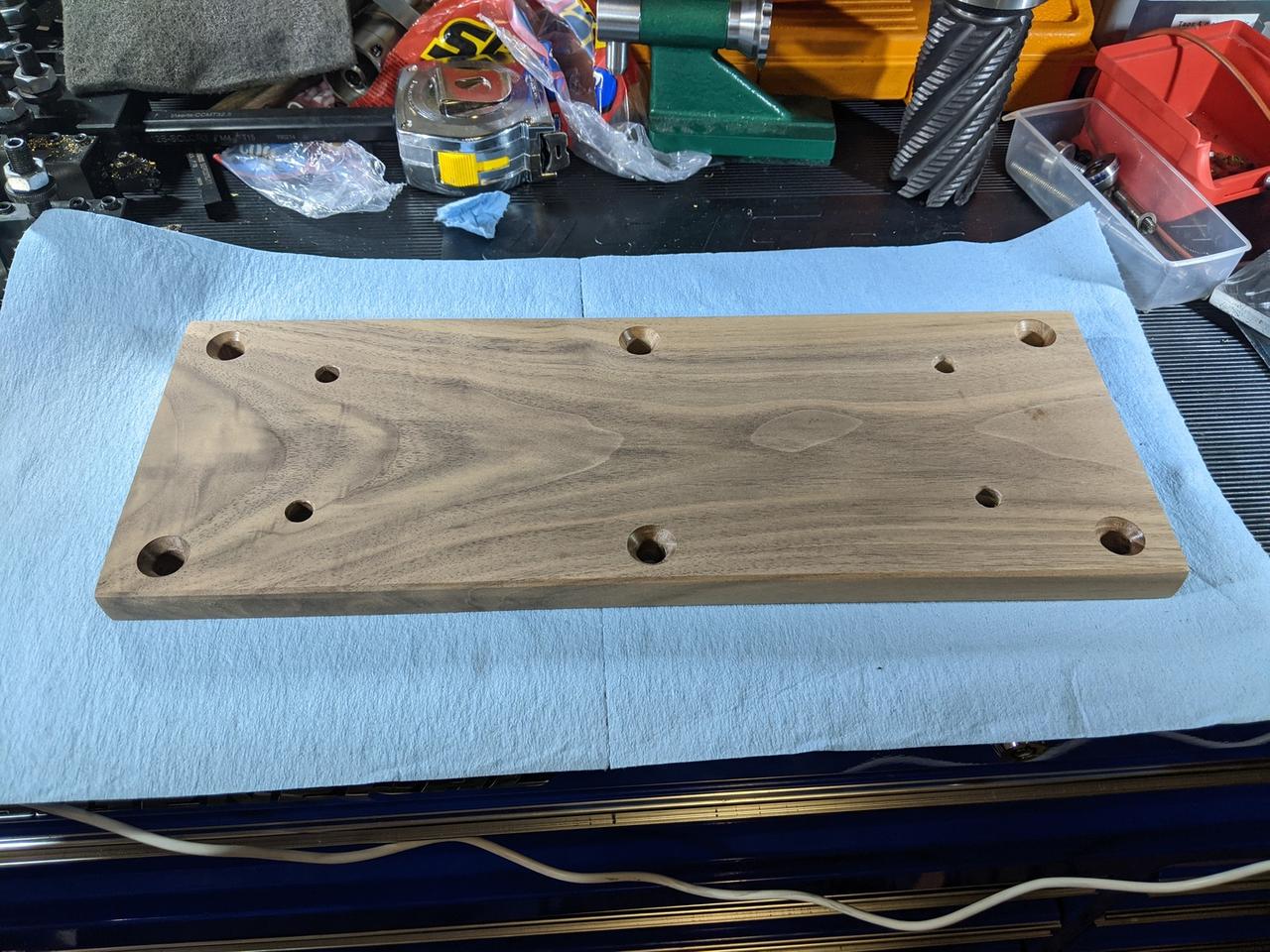
Next up, I made some little brass feet and then machined the wood:
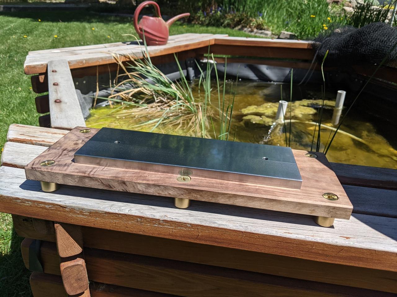
I hate wood. The tools to work with it are loud, the sawdust makes me sneeze and gives me sinus infections, and it's just not cool like metal is. I knew I wanted a wooden base, though. The brass, black walnut, and steel would look great together and the wood might soak up a bit of vibration.
I gave the wood a good sanding down (120 -> 180 -> 220 on an orbital sander):
And then started applying Tru-oil. I actually really screwed this up the first time. My coats were incredibly thick and weren't drying:
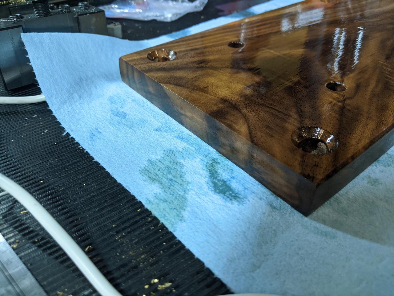
I kept applying coats this way until it all went wrong. I had to sand off all of the finish and then retry. This time, I used much lighter coats until the wood was in a somewhat happy state.
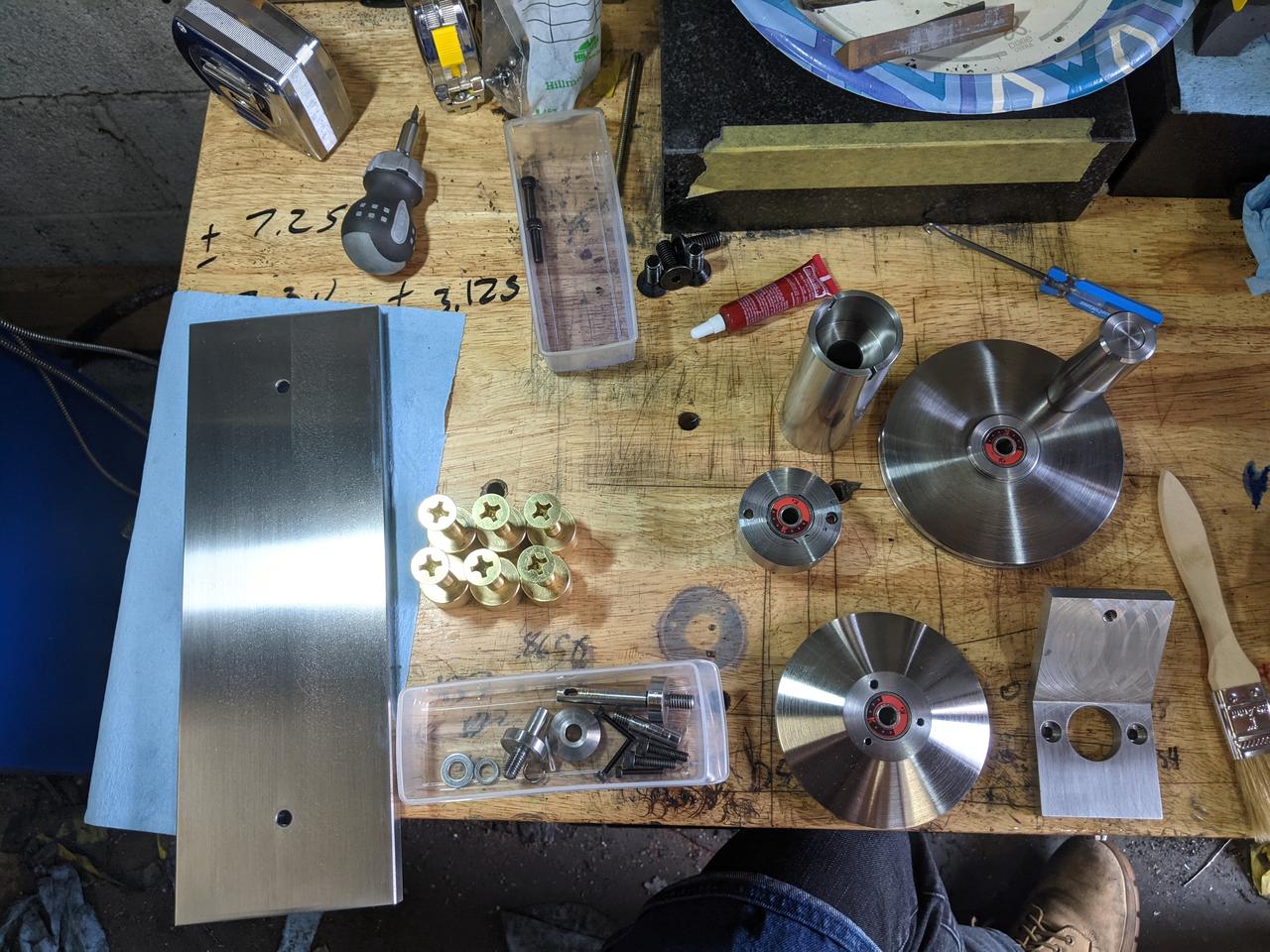
With that, it was time to sand and polish all of the remaining components. I'm not Clickspring, so this means that they got a bit of time with some 320 grit emery paper and some grey Scotchbrite. I hit the brass components with Brasso (which I had never used before and hadn't realized was INCREDIBLY SMELLY thanks to the ammonia) and then laid everything out:
Once the wood had dried out, it was time to put it together! Note that there are some small Sorbothane washers and bumpers on the feet to soak up the vibration, because this thing is heavily off-balance. If I can get my hands on some tungsten then I'll machine a counterweight. In the meantime, the Sorbothane does an admirable job of soaking up the vibrations.
And of course, here's a video of it winding a ball of yarn:
So that's it! The solid steel yarn winder. Hopefully you've enjoyed this. I'll probably be back with more projects in the future, but I think I'm just about done writing for now.
Comments
Comments powered by Disqus